
Geography. Modern illustrated encyclopedia. - M.: Rosman. Edited by prof. A. P. Gorkina. 2006 .
See what “conventional signs” are in other dictionaries:
Symbolic, line and background designations of terrain objects, combat and meteorological conditions, used on topographic and other geographical maps, as well as on graphic documents. Depending on the purpose, they distinguish... ... Marine Dictionary
Conventional signs- Conventional signs... Geographical atlas
Graphic, alphabetic and numerical designations of objects and terrain elements, operational tactical and meteorological conditions, used on topographic and other geographical maps, as well as on graphic documents. Depending on the… … Dictionary of emergency situations
Conventional signs- graphic symbols and standard abbreviations of explanatory inscriptions to them, used in military operational documents, on diagrams, maps, report cards, etc. to indicate the position of troops, rear units (units) ... ... A brief dictionary of operational-tactical and general military terms
conventional signs- sutartiniai ženklai statusas T sritis Gynyba apibrėžtis Vietovės objektų, kovinės ir meteorologinės situacijos žymėjimo žemėlapiuose ir kt. koviniuose grafiniuose dokumentuose ženklai. Pagal paskirtį jie būna taktiniai, topografiniai ir… … Artilerijos terminų žodynas
conventional signs- sutartiniai ženklai statusas T sritis ekologija ir aplinkotyra apibrėžtis Grafiniai simboliai, kuriais žemėlapiuose reiškiamas jų turinys. Simboliais vaizduojami fiziniai Žemės paviršiaus objektai (jų padėtis, kiekybiniai ir kokybiniai… … Ekologijos terminų aiškinamasis žodynas
Conventional signs- signs used in drawing up plans and diagrams of the crime scene and other places of investigative actions. They are a set of standard topographical signs and designations of objects found in investigative... ... Forensic encyclopedia
Conventional signs- symbolic line and background designations of terrain objects, combat and meteorological conditions, used on geographical maps and graphic documents. There are topographical, tactical, and meteorological ultrasonic systems. They can… … Glossary of military terms
CONVENTIONAL SIGNS- GENERAL INFORMATION ABOUT THE CONTINENTS Name of the continent Area in thousand square meters. km Coordinates of extreme points Highest altitude above sea level Lowest altitude from sea level Eurasia 54,870 north. m. Chelyuskin 77º43′ N. 104º18′ E south m.... ... Geographical atlas
Cartographic symbols are a system of symbolic graphic symbols used to depict various objects and phenomena, their qualitative and quantitative characteristics on maps. Conventional signs used on the map... ... Wikipedia
Books
- , Conventional signs for topographic plans. Scales 1: 5000, 1: 2000, 1: 1000 and 1: 500 Reproduced in the original author’s spelling of the 1973 edition (Nedra publishing house).… Category: Agricultural machinery Publisher: YOYO Media, Manufacturer: Yoyo Media,
- Symbols for topographic plans, Main Department of Geodesy and Cartography under Sova, Symbols of geodetic points, buildings, buildings and their parts, railways and structures attached to them, highways and dirt roads, hydrography, bridges, overpasses and... Category: Agricultural machinery Publisher: YOYO Media, Manufacturer:
Any card has its own special language - special symbols. Geography studies all these designations, classifies them, and also develops new symbols to designate certain objects, phenomena and processes. Having a general understanding of conventional cartographic signs is useful for absolutely everyone. Such knowledge is not only interesting in itself, but will certainly be useful to you in real life.
This article is devoted to conventional signs in geography, which are used in the preparation of topographic, contour, thematic maps and large-scale terrain plans.
ABC cards
Just as our speech consists of letters, words and sentences, so any map includes a set of specific symbols. With their help, topographers transfer this or that terrain onto paper. Conventional signs in geography are a system of special graphic symbols used to designate specific objects, their properties and characteristics. This is a kind of “language” of the map, created artificially.
It is quite difficult to say exactly when the very first geographical maps appeared. On all continents of the planet, archaeologists find ancient primitive drawings on stones, bones or wood, created by primitive people. This is how they depicted the area in which they had to live, hunt and defend themselves from enemies.
Modern symbols on geographic maps display all the most important elements of the area: landforms, rivers and lakes, fields and forests, settlements, communication routes, country borders, etc. The larger the image scale, the more objects can be plotted on the map . For example, on a detailed plan of the area, as a rule, all wells and sources of drinking water are marked. At the same time, marking such objects on a map of a region or country would be stupid and impractical.
A little history or how the symbols of geographical maps changed
Geography is a science that is unusually closely related to history. Let's delve into it to find out what cartographic images looked like many centuries ago.
Thus, ancient medieval maps were characterized by an artistic representation of the area with the widespread use of drawings as symbols. Geography at that time was just beginning to develop as a scientific discipline, therefore, when compiling cartographic images, the scale and outlines (borders) of area objects were often distorted.

On the other hand, all the drawings on the old drawings and portolans were individual and completely understandable. But these days you have to use your memory to learn what certain symbols on geographical maps mean.
From about the second half of the 18th century, there was a tendency in European cartography towards a gradual transition from individual perspective drawings to more specific plan symbols. In parallel with this, a need arose for a more accurate display of distances and areas on geographic maps.
Geography: and topographic maps
Topographic maps and terrain plans are distinguished by fairly large scales (from 1:100,000 or more). They are most often used in industry, agriculture, geological exploration, urban planning and tourism. Accordingly, the terrain on such maps should be displayed in as much detail and detail as possible.
For this purpose, a special system of graphic symbols was developed. In geography, it is also often called the “map legend.” For ease of reading and ease of memorization, many of these signs resemble the real appearance of the terrain objects they depict (from above or from the side). This system of cartographic symbols is standardized and mandatory for all enterprises that produce large-scale topographic maps.
The topic “Conventional signs” is studied in the school geography course in the 6th grade. To check the level of mastery of a given topic, students are often asked to write a short topographical story. Each of you probably wrote a similar “essay” at school. Sentences with symbols on geography look something like the photo below:

All symbols in cartography are usually divided into four groups:
- scale (area or contour);
- off-scale;
- linear;
- explanatory.
Let's take a closer look at each of these groups of signs.
Scale signs and their examples
In cartography, scale signs are those that are used to fill in any area objects. It could be a field, a forest or an orchard. Using these symbols on the map, you can determine not only the type and location of a particular object, but also its actual size.
The boundaries of area objects on topographic maps and site plans can be depicted as solid lines (black, blue, brown or pink), dotted or simple dotted lines. Examples of large-scale cartographic symbols are presented below in the figure:

Off-scale signs
If a terrain feature cannot be depicted on the real scale of a plan or map, then non-scale symbols are used. We are talking about too small things, for example, a windmill, a sculptural monument, a rock outcrop, a spring or a well.
The exact location of such an object on the ground is determined by the main point of the symbol. For symmetrical signs this point is located in the center of the figure, for signs with a wide base - in the middle of the base, and for signs based on a right angle - at the apex of such an angle.
It is worth noting that objects expressed on maps by out-of-scale symbols serve as excellent landmarks on the ground. Examples of off-scale cartographic symbols are presented in the figure below:

Linear signs
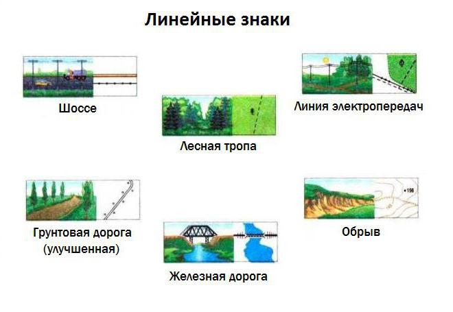
Sometimes the so-called linear cartographic signs are included in a separate group. It is not difficult to guess that they are used to designate linearly extended objects on plans and maps - roads, boundaries of administrative units, railways, fords, etc. An interesting feature of linear designations: their length always corresponds to the scale of the map, but the width is significantly exaggerated.
Examples of linear cartographic symbols are presented in the figure below.
Explanatory signs
Perhaps the most informative is the group of explanatory symbols. With their help, additional characteristics of the depicted terrain objects are indicated. For example, a blue arrow in a river bed indicates the direction of its flow, and the number of transverse strokes on a railroad symbol corresponds to the number of tracks.
As a rule, maps and plans are labeled with the names of cities, towns, villages, mountain peaks, rivers and other geographical features. Explanatory symbols can be numeric or alphabetic. Letter designations are most often given in abbreviated form (for example, a ferry crossing is indicated as the abbreviation “par.”).
Symbols of contour and thematic maps
A contour map is a special type of geographic map intended for educational purposes. It contains only a coordinate grid and some elements of a geographical basis.
The set of symbols for contour maps in geography is not very wide. The very name of these maps is quite eloquent: to compile them, only contour marks of the boundaries of certain objects - countries, regions and regions - are used. Sometimes rivers and large cities are also marked on them (in the form of dots). By and large, a contour map is a “silent” map, which is precisely intended to fill its surface with certain conventional symbols.
Thematic maps are most often found in geography atlases. The symbols of such cards are extremely diverse. They can be depicted as a color background, areas or so-called isolines. Diagrams and cartograms are often used. In general, each type of thematic map has its own set of specific symbols.
Map frames and coordinate lines. Sheets of topographic maps have three frames: inner, minute and outer. The inner frame is formed by segments of parallels that limit the map area from the north and south, and segments of meridians that limit it from the west and east. The values of latitude and longitude on the lines of the inner frame are associated with the nomenclature of the map and are written in each corner.
Between the inner and outer frames is a minute frame, on which are marked the divisions corresponding to one minute of latitude (left and right) and longitude (top and bottom). Dots on the frame mark tens of seconds.
The rectangular coordinate system on the map is represented by a kilometer grid formed by coordinate lines drawn through 1 km x And y. Values x And y, expressed in kilometers, are inscribed at the exits of the lines beyond the inner frame of the map.
Plans at scales 1:5000-1:500 with rectangular layout have only a grid of rectangular coordinates. Its lines are drawn every 10 cm.
Conventional signs. On plans and maps, terrain features are depicted with conventional symbols.
Conventional signs distinguish between contour, non-scale and linear.
Contour symbols depict objects whose shape and size can be conveyed on the scale of a plan (map). These include land (forests, gardens, arable lands, meadows), reservoirs, and on a larger scale - buildings and structures. The outlines of objects (contours) on the plan are shown with dotted lines or lines of a certain thickness and color. Signs indicating the nature of the object are placed inside the outline.
Out-of-scale symbols depict objects that need to be put on the plan, but cannot be depicted to scale (gas stations, wells, points of a geodetic network, etc.).
Linear symbols depict objects whose length is expressed on the plan scale, but whose width is not expressed (power and communication lines, pipelines, fences, paths).
To reflect the characteristics of the depicted objects, many symbols are accompanied by explanatory captions. So, when depicting a railway, indicate the height of the embankment and the depth of the excavation, as well as the track width on a narrow-gauge road. When depicting a highway, indicate its width and coating material; when depicting communication lines - the number of wires and their purpose; when depicting forests - tree species, average height, thickness of trunks and distance between trees.
Relief image. On maps and plans, the relief is depicted using contour lines, elevation marks and symbols.
Horizontals- lines of section of the earth's surface by equidistant level surfaces. In other words, horizontal lines are lines of equal heights. Horizontal lines, like other terrain points, are projected onto a level surface Q and applied to the plan (Fig. 4.3).
Rice. 4.3. Horizontals: h– height of the relief section; d– laying
Difference h heights of adjacent horizontal lines, equal to the distance between secant surfaces, is called relief section height. The value of the section height is signed at the bottom frame of the plan.
The horizontal distance between adjacent horizontal lines is called mortgage. The minimum position in this place is perpendicular to the horizontal lines, - laying of the slope. The lower the slope, the steeper the slope.
The direction of the slope is indicated berg strokes- short strokes at some horizontal lines, directed towards the descent. On individual horizontal lines, their heights are written in their breaks so that the top of the numbers points in the direction of the rise.
Horizontal lines with round height values are made thicker, and to reflect relief details they are used semi-horizontal– dashed lines corresponding to half the height of the relief section, as well as auxiliary horizontal lines with short strokes, carried out at an arbitrary height.
The depiction of the relief with horizontal lines is supplemented by inscribing elevation marks on the plan near characteristic points of the relief and with special symbols depicting cliffs, rocks, ravines, etc.
The main landforms are mountain, basin, ridge, hollow and saddle (Fig. 4.4).

Rice. 4.4. Main landforms: A– mountain; b– basin; V– ridge; G- hollow; d– saddle; 1 – watershed line; 2 – drainage line.
Mountain(hill, hill, mound, hill) is depicted by closed horizontal lines with berg strokes facing outwards (Fig. 4.4, A). The characteristic points of a mountain are its top and points at the bottom.
Basin(depression) is also depicted by closed horizontal lines, but with berg strokes facing inward (Fig. 4.4, b). The characteristic points of the basin are the points on its bottom and along the edge.
Ridge- elongated hill. It is depicted as elongated horizontal lines going around the crest of the ridge and running along its slopes (Fig. 4.4, V). The berghstrokes, like those of the mountain, face outwards. The characteristic line of a ridge is that running along its crest watershed line.
Hollow(valley, gorge, ravine, gully) - a depression elongated in one direction. Depicted as elongated horizontal lines with bergschriches facing inward (Fig. 4.4, G). The characteristic line of the valley is drain line(thalweg) - a line along which water runs.
Saddle(pass) - a depression between two hills (Fig. 4.4, d). There are hollows on both sides of the saddle. A saddle is the intersection of the watershed and drainage lines.
A asphalt (road surface material)
art.k. artesian well
B cobblestone (coating material expensive)
ber. birch (forest species)
bl.-p blockpO st (railway)
br. ford
mass grave mass grave
IN viscous (river bottom soil)
water water tower
G gravel (road surface material)
gazpr. gas pipeline
RTS repair and technical station
g.prokh. mountain pass
gsp. hospital
(year-sol) bitter salt water
hydroelectric power station hydroelectric power station
D wooden (material of bridge, dam)
(Sol.) salty water
reinforced concrete reinforced concrete (bridge material, dams)
ist. source
TO stone (material of bridge, dam)
TO. well
Kam. quarry, stone
class key, spring
forest forester's house
foliage larch (forest species)
mash. machine-building plant
MTF dairy farm
island, islands, islands
A topographic map is a very interesting and extremely rich drawing. The famous Russian traveler Semenov-Tyan-Shansky said this about this: “The map is more important than the text, since it often speaks much more clearly, clearly and concisely than the best text.” And indeed it is. Each sheet of a topographic map contains a wealth of material, the description of which would require many hundreds of pages in a book.
A map is a graphic description of an area. Just as words are made up of individual letters, and groups of words express thoughts, so a map of an area is created from individual topographical symbols, arranged in a certain order.
Conventional topographic signs, like the maps themselves, have come a long way in their development. Images of local objects on maps of early eras had a “pictorial” character. Each item was conveyed in a drawing that was understandable without any explanation. Cities, forests, and fortresses were depicted as they were observed in nature. This image is often used today in tourist plans and maps (Fig. 30).
Figure 30.
Over time, the image of settlements on maps changed first from a drawing to a plan image, and then from a drawing to conditionaltopographic sign.
So, topographical signs are the real alphabet of the map. Without knowing the symbols, you cannot read a map, just as you cannot read a book without knowing the letters. With the help of symbols on the map, the actual picture of the area is clearly conveyed.
Most of the topographical symbols in their outline resemble the appearance of the local objects depicted, which makes them relatively easy to remember. Conventional signs are constantly being improved, but fundamental changes in their outline and form do not occur. Moreover, many countries now use almost the same signs. And this already suggests that the alphabet of maps is becoming international. And if you learn to read our map well, then after a little practice you will be able to successfully use any foreign one.
The explanatory properties of topographic signs also include their color, which gives the map clarity. The colors adopted for some conventional signs correspond to the natural color of the depicted objects. Thus, forests, shrubs, gardens and parks are depicted as green; seas, rivers, lakes, wells, springs, swamps - blue; relief elements - brown. These are traditional colors used on maps all over the world.
Conventional signs depicting the same local objects on large and medium scale maps are identical in their outline and differ only in size.
Conventional signs are divided into large-scale, non-scale and explanatory.
Scale, or contour,conditionaltopographic signs are used to depict local objects whose size can be expressed on a map scale, that is, their dimensions (length, width, area) can be measured on the map. For example: lake, meadow, large gardens, residential areas. The contours (external boundaries) of such local objects are depicted on the map with solid lines or dotted lines, forming figures similar to these local objects, but only in a reduced form, that is, on the scale of the map. Solid lines show the contours of neighborhoods, lakes, wide rivers, and the contours of forests, meadows, and swamps are dotted.
Figure 31.
Constructions and buildings expressed on the scale of the map are depicted with figures similar to their actual outlines on the ground and are painted over in black. Figure 31 shows several on-scale (a) and out-of-scale (b) symbols.
Off-scale symbols are used to depict small local objects that cannot be expressed on a map scale - free-standing trees, houses, wells, monuments, etc. When depicting them on a map scale, they would appear in the form of a point. Examples of depicting local objects with out-of-scale symbols are shown in Figure 31. The exact location of these objects, depicted with out-of-scale symbols (b), is determined by the center of the symmetrical figure (7, 8, 9, 14, 15), in the middle of the base of the figure (10, 11) , at the top of the corner of the figure (12, 13). Such a point on the figure of an off-scale symbol is called the main point. In this figure, the arrow shows the main points of symbols on the map.
It is useful to remember this information in order to correctly measure the distance between local objects on the map.
Explanatory topographic signs serve for additional characterization of local objects and are used in combination with large-scale and non-scale signs. For example, a figurine of a coniferous or deciduous tree inside the outline of a forest shows the dominant tree species in it, an arrow on a river indicates the direction of its flow, etc.
In addition to signs, maps use full and abbreviated signatures, as well as digital characteristics of some objects. For example, the signature “mash.” with a plant sign means that this plant is a machine-building plant. The names of settlements, rivers, mountains, etc. are fully signed.
Digital symbols are used to indicate the number of houses in rural settlements, the height of the terrain above sea level, the width of the road, the characteristics of the load capacity and the size of the bridge, as well as the size of trees in the forest, etc. Digital symbols related to conventional relief signs are printed in brown. , width and depth of rivers - blue, everything else - black.
Let us briefly consider the main types of topographic symbols for depicting the area on the map.
Let's start with the relief. Due to the fact that observation conditions largely depend on its nature, the terrain's passability and its protective properties, the terrain and its elements are depicted on all topographic maps in great detail. Otherwise, we could not use the map to study and evaluate the area.
In order to clearly and completely imagine the area on the map, you must first of all be able to quickly and correctly determine on the map:
Types of unevenness of the earth's surface and their relative location;
Mutual elevation and absolute heights of any terrain points;
The shape, steepness and length of the slopes.
On modern topographic maps, the relief is depicted by horizontal lines, that is, curved closed lines, the points of which are located on the ground at the same height above sea level. To better understand the essence of depicting relief with horizontal lines, let’s imagine an island in the form of a mountain, gradually flooded with water. Let us assume that the water level sequentially stops at equal intervals, equal in height to h meters (Fig. 32). Then each water level will have its own coastline in the form of a closed curved line, all points of which have the same height. These lines can also be considered as traces of the section of uneven terrain by planes parallel to the level surface of the sea, from which heights are calculated. Based on this, the height distance h between the secant surfaces is called the section height.
Figure 32.
So, if all lines of equal heights are projected onto the level surface of the sea and depicted to scale, then we will receive an image of the mountain on the map in the form of a system of curved closed lines. These will be the horizontal lines.
In order to find out whether it is a mountain or a basin, there are slope indicators - small lines that are drawn perpendicular to the horizontal lines in the direction of the descent of the slope.
Figure 33.
The main (typical) landforms are presented in Figure 32.
The height of the section depends on the scale of the map and the nature of the relief. The normal height of the section is considered to be a height equal to 0.02 of the map scale, that is, 5 m for a map of scale 1:25,000 and, accordingly, 10, 20 m for maps of scales 1: 50,000, 1: 100,000. Contour lines on the map corresponding to those established for below the height of the section, are drawn in solid lines and are called main or solid horizontal lines. But it happens that at a given section height, important details of the relief are not expressed on the map, since they are located between the cutting planes. Then half semi-horizontal lines are used, which are drawn through half the main height of the section and are plotted on the map with broken lines. To determine the count of contours when determining the height of points on the map, all solid contours corresponding to five times the height of the section are drawn thickly (thickened contours). So, for a map of scale 1: 25,000, each horizontal line corresponding to the section height of 25, 50, 75, 100 m, etc. will be drawn as a thick line on the map. The main section height is always indicated below the south side of the map frame.
The altitudes of the terrain depicted on our maps are calculated from the level of the Baltic Sea. The heights of points on the earth's surface above sea level are called absolute, and the elevation of one point over another is called relative elevation. Contour marks - digital inscriptions on them - indicate the height of these terrain points above sea level. The top of these numbers always faces the upward slope.
Figure 34.
Marks of command heights, from which the terrain from the most important objects on the map (large settlements, road junctions, passes, mountain passes, etc.) is better visible than from others, are marked in large numbers.
Using contour lines you can determine the steepness of slopes. If you look closely at Figure 33, you can see from it that the distance between two adjacent contour lines on the map, called the lay (at a constant section height), changes depending on the steepness of the slope. The steeper the slope, the smaller the overlay and, conversely, the lower the slope, the greater the overlay. The conclusion follows from this: steep slopes on the map will differ in the density (frequency) of contours, and in flat places the contours will be less frequent.
Usually, to determine the steepness of the slopes, a drawing is placed in the margins of the map (Fig. 35). Along the lower base of this scale are numbers that indicate the steepness of the slopes in degrees. The corresponding values of the deposits on the map scale are plotted on perpendiculars to the base. On the left side, the depth scale is constructed for the main section height, on the right - at five times the section height. To determine the steepness of the slope, for example, between points a-b (Fig. 35), you need to take this distance with a compass and put it on the scale and read the steepness of the slope - 3.5°. If it is necessary to determine the steepness of the slope between the thickened horizontal lines, then this distance must be set aside on the right scale and the steepness of the slope in this case will be equal to 10°.
Figure 35.
Knowing the properties of contours, you can determine from the map the shape of various types of slopes (Fig. 34). For a flat slope, the depths will be approximately the same throughout its entire length; for a concave slope, they increase from the top to the bottom; and for a convex slope, on the contrary, the formations decrease towards the bottom. In wavy slopes, the positions change according to the alternation of the first three forms.
When depicting relief on maps, not all of its elements can be expressed as contours. So, for example, slopes with a steepness of more than 40° cannot be expressed as horizontals, since the distance between them will be so small that they will all merge. Therefore, slopes that have a steepness of more than 40° and are steep are indicated by horizontal lines with dashes (Fig. 36). Moreover, natural cliffs, ravines, gullies are indicated in brown, and artificial embankments, recesses, mounds and pits are indicated in black.
Figure 36.
Let's consider the basic conventional topographical signs for local objects. Settlements are depicted on the map while maintaining external boundaries and layout (Fig. 37). All streets, squares, gardens, rivers and canals, industrial enterprises, outstanding buildings and structures of landmark significance are shown. For better clarity, fire-resistant buildings (stone, concrete, brick) are painted orange, and blocks with non-fire-resistant buildings are painted yellow. The names of settlements on maps are written strictly from west to east. The type of administrative significance of a settlement is determined by the type and size of the font (Fig. 37). Under the signature of the name of the village you can find a number indicating the number of houses in it, and if there is a district or village council in the settlement, the letters “RS” and “SS” are additionally placed.
Figure 37 – 1.
Figure 37 – 2.
No matter how poor the area is in local objects or, on the contrary, saturated, there are always individual objects on it that, by their size, stand out from the rest and are easily identified on the ground. Many of them can be used as guides. This should include: factory chimneys and prominent buildings, tower-type buildings, wind turbines, monuments, gas pumps, signs, kilometer posts, free-standing trees, etc. (Fig. 37). Most of them, due to their size, cannot be shown on the scale of the map, so they are depicted on it as out-of-scale signs.
The road network and crossings (Fig. 38, 1) are also depicted with out-of-scale symbols. Data on the width of the roadway, road surface, indicated on conventional signs, make it possible to evaluate their throughput, load capacity, etc. Depending on the number of tracks, railways are indicated by dashes across the conventional road sign: three dashes - three-track, two dashes - double-track railway . Stations, embankments, excavations, bridges and other structures are shown on railways. For bridges longer than 10 m, its characteristics are signed.
Figure 38 – 1.
Figure 38 – 2.
Figure 39.
For example, the signature on the bridge ~ means that the length of the bridge is 25 m, the width is 6 m, and the load capacity is 5 tons.
Hydrography and structures associated with it (Fig. 38, 2), depending on the scale, are shown in greater or less detail. The width and depth of the river is written as a fraction 120/4.8, which means:
The river is 120 m wide and 4.8 m deep. The speed of the river flow is shown in the middle of the symbol with an arrow and a number (the number indicates the speed of 0.1 meters per second, and the arrow indicates the direction of the flow). On rivers and lakes, the height of the water level during low water (water line mark) in relation to sea level is also indicated. For fords it is signed: in the numerator - the depth of the ford in meters, and in the denominator - the quality of the soil (T - hard, P - sandy, V - viscous, K - rocky). For example, br. 1.2/k means that the ford is 1.2 m deep and the bottom is rocky.
Soil and vegetation cover (Fig. 39) is usually depicted on maps with large-scale symbols. These include forests, shrubs, gardens, parks, meadows, swamps, salt marshes, as well as sand, rocky surfaces, and pebbles. Its characteristics are indicated in the forests. For example, for a mixed forest (spruce with birch) the numbers are 20/0.25 - this means that the average height of the trees in the forest is 20 m, their average thickness is 0.25 m, and the average distance between tree trunks is 5 meters.
Figure 40.
Swamps are depicted depending on their passability on the map: passable, difficult to pass, impassable (Fig. 40). Passable swamps have a depth (to solid ground) of no more than 0.3-0.4 m, which is not shown on maps. The depth of impassable and impassable swamps is written next to the vertical arrow indicating the location of the measurement. On the maps, the corresponding symbols show the cover of the swamps (grass, moss, reed), as well as the presence of forests and shrubs on them.
Lumpy sands differ from smooth sands and are indicated on the map with a special symbol. In the southern steppe and semi-steppe regions there are areas with soil richly saturated with salt, which are called salt marshes. They are wet and dry, some are impassable and others are passable. On maps they are indicated by conventional symbols - blue “shading”. An image of salt marshes, sands, swamps, soil and vegetation cover is shown in Figure 40.
